
The AutoCAD bad practices mentioned in this list are some of the very common ones that are often seen in drawing offices.
The list is compiled based on responses from SourceCAD blog subscribers and LinkedIn connections, a big thanks to all of them for sharing their pick on this topic.
So, here is our list of AutoCAD bad practices that you should avoid.
Putting objects on the Defpoints layer
It doesn’t make any sense to put an object on the Defpoint layer that you don’t want to plot, let me tell you why.
The Defpoint layer is created automatically when you add dimension and it is always a no-plot layer, you can’t make it a “plot” layer.
So, putting objects that you don’t want to plot on this layer may seem like a good thing but what about rare instances where you may want to plot objects of the Defpoints layer?
In that case, you can’t turn the plot option ON for the Defpoints layer.
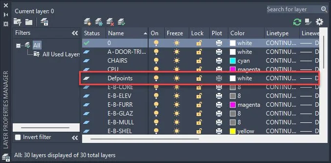
So, it makes more sense to create a new layer, call it “no-plot” or something similar and put your objects there.
Now you can turn off the plot for this layer and when required you can turn it on as well.
Besides you can create unlimited layers in AutoCAD so there is no point in trying to squeeze the maximum output from your existing list of layers.
Not assigning object properties by layer
I am sure you must have received drawings with blocks and other objects assigned to a particular layer but these objects are still using their custom properties not as per layer.
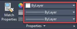
When you change layer properties these objects just stand out and don’t inherit properties from layers and their properties remain unchanged which may not always be good.
Now in some instances, you may want to add custom properties that are different from the layer, and that’s totally fine but try to assign properties by layer for as many objects as possible using.
Making all objects on layer 0
Why would you do that?
AutoCAD offers a great way of managing drawing objects using layers which also helps in controlling the properties of multiple objects directly using layer properties.
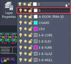
This is simply a bad practice which is seen in a novice or a lazy drafter and it should also be avoided wherever possible.
Not using layering standards
As far as possible try to use layering standards such as AIA or your company standard.
This ensures consistency when the drawing is transferred to other contractors.
If consistent standards are not followed, then you might end up with drawings having different naming standards that need to be translated before they can be used properly thus killing extra work hours.
70 lessons| Easy Level
If you are absolute beginner of AutoCAD then you can get started right from scratch using this free course.
Placing objects on the wrong layers
This issue can simply be avoided by reviewing drawings before submission.
Sometimes not all of the drawing objects are placed on the correct layer.
For example; not placing all of the doors in a drawing on it's layer and other similar situations.
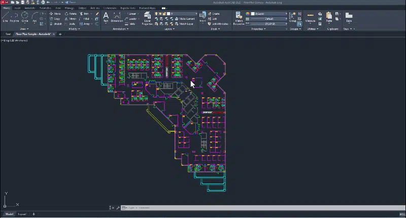
One easy way to check if all your objects are on their respective layer is by using the “Layer Walk” option for key layers or all layers (if you have a smaller drawing) as shown in the following animated GIF.
Not specifying Drawing units
This is a complete rookie mistake where you simply start with whatever template AutoCAD started your drawing with.
Just select a standard template that your company uses or use the one from AutoCAD default templates and specify the drawing unit, precision and length format like decimal or architectural before you begin your drawing.
It may seem like changing these settings later is easy but it’s not, changing the drawing unit in AutoCAD is not immune to errors so taking care of this before you begin your drawing is a good practice.
Not using annotative scales
Using the different scales of an object for different viewports and putting them on different layers is an obsolete technique.
Annotative property in AutoCAD is introduced to get rid of this issue and to make drawing scale transition a seamless task but still, most of the drafters try to avoid using annotative scale despite its great features.
So, when adding objects like dimensions and text directly in model space drawings, create them using the annotative property.
Not Locking Viewports in Paperspace
When you are done changing the scale of a viewport in paper space then you should always lock that viewport to avoid changing its scale accidentally.
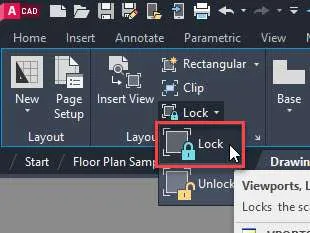
The accidental change of viewport scale may go unnoticed and down the road, you may have to spend extra time trying to correct it or figure out what went wrong in your drawing.
Blocks are not created on layer 0
Many drafters place AutoCAD blocks on a custom layer other than layer 0, but it should be avoided and blocks should be created on layer 0.
Layer 0 has a special significance when it comes to creating blocks and the properties of a block will be inherited from layer only when you create it on layer 0.
So, unless you want a block with a specific set of properties that doesn’t change based on its layer, put it on layer 0.
Not putting XREF on a separate layer
As far as possible always try to put Xref on a separate layer dedicated to only Xref and also ensure that the layer is not layer 0.
In this way, you can control the properties of X-refs in a better way and also it becomes easier to manage these external references in drawings.
Also, prefix the layer containing Xref with X or Z to keep it at the bottom of the layer list.
Toggling the visibility of all Xref’s also becomes easy when they are put on dedicated layers and with a prefix identifying the Xref layer clearly, it becomes easier to manage it too.
Not using eTransmit for drawing containing Xref
Generally, Xref’s of a drawing are saved on multiple network drives (or local drives) and if you want to send a drawing containing multiple Xref then eTransmit is the best option.
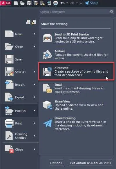
Sending all Xref manually is not a good idea as it may cause broken file paths and missing references.
To ensure all contents of a drawing containing xref are sent use AutoCAD eTransmit tool as it creates a zip file of all Xref’s and as the process is done automatically it extracts all objects from their respective locations and there is no chance of missing any file.
Making Xref drawings on layer 0
Putting objects on layer 0 and then “Xref’ing” that drawing into another is not a good practice.
If you do that then the layer properties of the Xref are not copied from its main drawing.
But if you create a drawing on a layer other than layer 0 and then attach that drawing in another drawing as an Xref then it will be copied along with its layers and layer properties.
So you can later change the Xref properties using its dedicated layer.
70 lessons| Easy Level
If you are absolute beginner of AutoCAD then you can get started right from scratch using this free course.
Using complete commands instead of aliases
It is better to use command aliases instead of complete commands on the AutoCAD command line.
Moreover, if autocomplete feature of the command line is ON then you need not enter the complete command as it will automatically show you the relevant commands based on the first few letters you type.
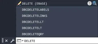
You can also try using the command line more often as it is quicker than using the ribbon interface, but this is a general suggestion as in the end it just comes down to personal preference.
Copy and paste from drawing of different versions or software
This is a thing that can’t be avoided always but if possible it should be avoided.
Copying and pasting data from drawings of different versions or from non-native DWG files created with other software can bring with it unnecessary clutter in the drawing database which will simply bloat your drawing file.
The purge command can clean the AutoCAD drawings but it may not be able to clean all the redundant data types.
Not using associative hatch
Whenever you hatch an area in the drawing try to keep it associative so that changing the boundary changes the associated hatch region as well.
Also, try not to explode the hatch because once exploded a hatch can’t be modified using the hatch editor tab and it creates a mess of lines and other geometries that only look like a hatch but don’t work like one.
Not using an Associative array
Using an associative array you can keep the option of modifying the array open anytime you want.
If you explode an array or create a nonassociative array then it can’t be modified later.

So try to avoid the bad practice of making non-associative arrays.
Not Purging drawing regularly
Many drafters tend to overlook the importance of PURGE command.
It is always a good practice to use the PURGE command for cleaning AutoCAD drawing and removing objects like DGN linetypes, unused objects and more.
It is always recommended that you purge your drawings especially before you share them so that you can keep only the necessary data in them.
Not using the OVERKILL command
Using this command you can make your drawing cleaner by removing overlapping geometries and combining separate entities into polylines.
In general, you should avoid using several smaller pieces of lines for closed geometries and instead use polylines for the same.
But if you’ve already used several broken lines then you can combine them all into one polyline using the OVERKILL command.
Avoid different dimension styles in a drawing
This is a bad practice that makes the drawing look very unprofessional.
Whenever possible use one main dimension style for your primary dimensions and for other dimensions with small variations you can use dimension overrides.
Changing dimension value rather than drawing accurately
This is a rookie mistake but an experienced CAD drafter is also not immune to this.
Always make your drawing accurate so that the dimensions show the “real” value and don’t trick anyone by changing the dimension value to whatever it is supposed to be.
If the dimensions are not showing what they should be then modify your drawing to make it right not the dimensions.
Keeping all object snap modes ON
New CAD users may find it useful to keep all object snap modes ON to enable the selection of any snap point, but it is certainly a bad practice.
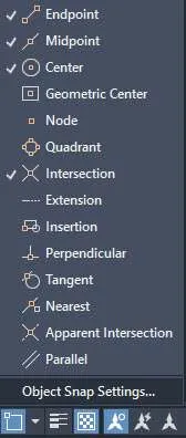
It causes your drawing to snap to incorrect points which are in close proximity which will eventually make inaccurate drawings.
To avoid this error try to keep only the required snap points ON or try using Shift right-click (object snap override) for selecting specific snap points.
Add text notes in paper space
Add text entities like notes, tables, title blocks and other content containing text in the paper space.
70 lessons| Easy Level
If you are absolute beginner of AutoCAD then you can get started right from scratch using this free course.
The biggest advantage of using paper space for text is the use of paper text height, which means you can avoid using the annotative property for these texts and you can directly set the size of text as per the size of paper in use.
I am not recommending that you completely avoid using text in model space, you should not do that.
Not all texts can be added in paper space so when you add text in the model space make it annotative so that the size of all texts remains consistent throughout the drawing.
Avoid tracing 3D drawings to generate 2D
This creates a really big problem which may not be visible from the plan view but as soon as you change the view to look at the Z axis you will find that the drawing is not completely flat.
Making corrections in this type of drawing is a time taking thing and it is something that could have been totally avoided in the first place by making everything on XY.
Using MTEXT columns
This might be a thing of personal preference but here is the recommendation.
Use separate blocks of Mtext for separate columns rather than using one large Mtext block and separating it into columns using its native “column” option.
Using separate Mtext blocks you get more control over the text rather than using the “column” feature of Mtext.
Also, whenever working with several Mtext blocks make sure they align along rows and columns because unaligned text blocks just look unprofessional.
Summary
That was our list of AutoCAD bad practices that everyone should avoid.
Many new inputs are added in this article from the comments and I must say they were pretty detailed and super relevant.
So, I have made these suggestions part of the article.
Finally I am looking forward to more input from you, share the bad practices that you often see in your office and what annoys you most, just mention it in the comments down below.


I am IT, not ENG – working in MFG environment.
I have concerns about a practice my ENG team is using,
The practice involves multi-layer drawings.
Let me try to illustrate the practice in simplified format –
Imagine a multi-layer drawing(#1) with three layers(1,2,3)
Layer 1{Posts}:
Shows 4 ‘Posts’ (circles)– 2 across top of form – labeled post1 and post2
2 posts across the bottom of the form – label postA & postB.
Layer2{wiresParallel}:
Shows 2 lines representing wiring connections
One from post1 to postA
&
One from post2 to postB.
Layer3(wiresCrossed):
Also showing 2 lines in same style as layer 2 representing variation of the connection where
One wire runs from post1 to postB
And 1 wire from post2 to postA.
Now imagine a product where the 2 wiring configurations cause different functionalities, both desirable.
In manufacturing of this product is a ‘wiring operator’ who will need to see an illustration of what he is supposed to do for each unit.
When a unit has attribute ‘Parallel’ – an IT application is supposed to open drawing#1 showing layer1 and layer 2
When the unit has attribute ‘Crossed’ – the IT application is supposed to open drawing#1 showing layer 1 and layer 3
Looking at internet content describing it –
I would say the standard intent of a multi-layer drawing is to construct a single illustration(1)
Compiled from all the layers – to be viewed.
But my ENG team sees the multi-layer drawing as a multifaceted diagram describing a variety of possibilities.
That is easy for ENG to make, and often shows what MFG needs to see –
as long as IT can manipulate the attributes and layers correctly with extra time and money to provide an ‘application’
to precisely open the drawing with only needed layers.
Is this practice good form?
Are there other AutoCad practices that can help with this?
Is there any tool in AutoCad–
where a complex multilayer drawing that describes multiple different (mutually exclusive) configurations –
Could somehow generate(and name) an array of all the valid ‘drawing permutations’ that might flow from it?
Thank you.
Hi Darryl,
It is hard to understand what you are referring here. I would like to request if you could please share a video of the same so that I can help you.
You can send the video at [email protected]
I am IT, not ENG – working in MFG environment.
I have concerns about a practice my ENG team is using,
The practice involves multi-layer drawings.
Let me try to illustrate the practice in simplified format –
Imagine a multi-layer drawing(#1) with three layers(1,2,3)
Layer 1{Posts}:
Shows 4 ‘Posts’ (circles)– 2 across top of form – labeled post1 and post2
2 posts across the bottom of the form – label postA & postB.
Layer2{wiresParallel}:
Shows 2 lines representing wiring connections
One from post1 to postA
&
One from post2 to postB.
Layer3(wiresCrossed):
Also showing 2 lines in same style as layer 2 representing variation of the connection where
One wire runs from post1 to postB
And 1 wire from post2 to postA.
Now imagine a product where the 2 wiring configurations cause different functionalities, both desirable.
In manufacturing of this product is a ‘wiring operator’ who will need to see an illustration of what he is supposed to do for each unit.
When a unit has attribute ‘Parallel’ – an IT application is supposed to open drawing#1 showing layer1 and layer 2
When the unit has attribute ‘Crossed’ – the IT application is supposed to open drawing#1 showing layer 1 and layer 3
Looking at internet content describing it –
I would say the standard intent of a multi-layer drawing is to construct a single illustration(1)
Compiled from all the layers – to be viewed.
But my ENG team sees the multi-layer drawing as a multifaceted diagram describing a variety of possibilities.
That is easy for ENG to make, and often shows what MFG needs to see –
as long as IT can manipulate the attributes and layers correctly with extra time and money to provide an ‘application’
to precisely open the drawing with only needed layers.
Is this practice good form?
Are there other AutoCad practices that can help with this?
Is there any tool in AutoCad–
where a complex multilayer drawing that describes multiple different (mutually exclusive) configurations –
Could somehow generate(and name) an array of all the valid ‘drawing permutations’ that might flow from it?
Thank you.
Hi Darryl,
It is hard to understand what you are referring here. I would like to request if you could please share a video of the same so that I can help you.
You can send the video at [email protected]