
In recent years, Autodesk Revit has become the most common BIM software among architects, engineers, and construction professionals for designing, documenting, and constructing structures.
Whether you're working on Architectural, Structural, MEP or General design projects, mastering Revit can significantly enhance your efficiency.
So, to make you even more efficient we have created a collection of our top Revit tips and tricks that you should try.
Revit Architecture tips
Let's start with Revit architecture tips.
Tip 1: Working with multiple views
You can create multiple views in a single window to see how the design looks from different perspectives.
For example, if you are preparing a plan view of your design, it will be helpful if you could see how the drawing looks in 3D isometric view.
This will allow you to fix any issues in real time.
To get multiple views type WT and press enter key to tile the window and type ZA to zoom all.
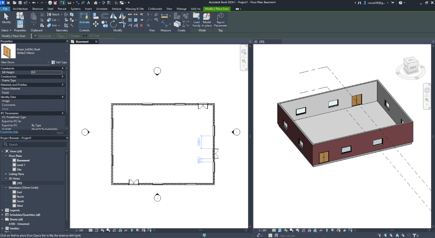
The tiled view will look like the image shown above.
Tip 2: Use pin to lock the drawing
As you build the design, the drawing will become more and more complex.
Due to this complexity, it is easy to unknowingly move any object from the drawing which may cost you time and money down the road.
So, you can avoid this issue by locking your drawing.
66 lessons| Easy Level
This course is for an absolute beginner of Revit architecture software. If you want to learn using simple bite sized Revit tutorials and video lessons then this course is for you.
To do that you can use the Pin option to lock parts of the drawing or objects in the drawing space.
This will restrict the unwanted movement of the objects.
As in the example shown below the grids drawn are pinned into the drawing.
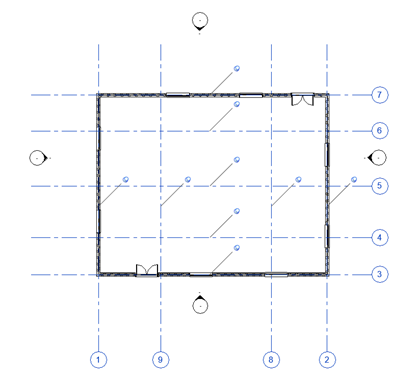
To pin down the drawing, select the object(s) from the drawing area then on the ribbon palette under modify tab you can find the option PIN in the modify panel as shown in the image below.

Alternatively, you can also use the shortcut “PN” then select the object from the drawing area to pin it in the drawing.
Tip 3: Use visibility and graphics settings
When the drawing gets complex you should start using the Visibility and Graphics setting.
With this setting you can control the visibility of all the objects in the drawing.
You can turn off the unused or unwanted objects from the drawing so that you have a clear workspace to work with.
If the list of objects feels longer you can use the filter to filter the objects based on discipline as shown in the image below.
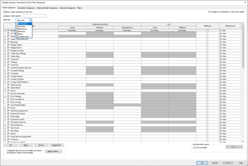
You can access the visibility graphics option in Revit by using the following three methods:
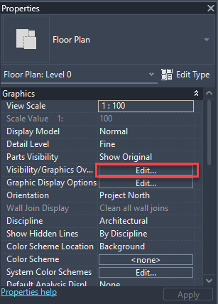
1. Click on the edit icon near the Visibility/Graphics override option in the properties panel as in the image below.
2. Click on the Visibility/Graphics icon under graphics panel from the view tab in the ribbon palette as given in the image below.

3. You can type the short cut VG to open the Visibility/Graphics override menu without selecting any object.
Tip 4: Creating view template
Changing the view settings every time for a new view you make is not practical and obviously a time-consuming thing.
So, you should make a view with all your settings and then save it as a template with a custom name.
The next time you need to create a view, you can simply use this template and all its settings will apply to it.
To create a view template, you need to go to the ribbon palette then click on the view tab and click on the View templates drop down from where you can access Create Template from current view option as shown in the image below.
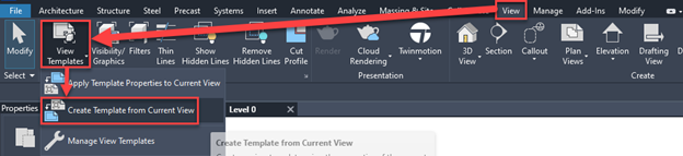
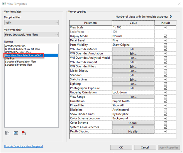
You can enter the required name for the View Template and click OK.
The new view template will show up on the list as shown in the figure below.
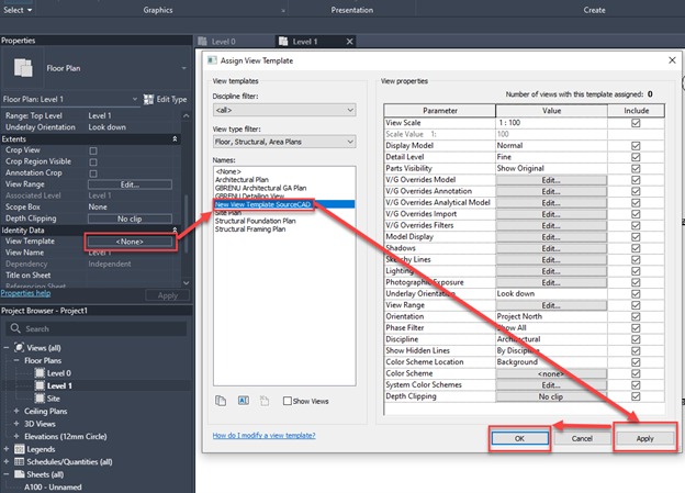
As you have created with the view template, you can now apply the view template to any views in Revit.
To set the view template, you can select the view template option in properties palette of a view then select the required view template, then click apply and click okay as shown in the figure below.
Tip 5: Linking Revit and CAD models
There is an exceptional feature to link CAD files into Revit including linking other files like DWG and IFC from different software directly into Revit.
After linking the files, you can use them as a reference in Revit and draw your designs on top of it.
To insert the external files click on the Insert tab in the ribbon palette and select the file type you want to link from available options as shown in the following image.
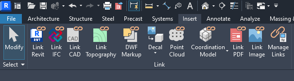
You can manage the links that are attached in a drawing from the Manage link icon available under Insert tab in the Ribbon Palette as shown in the image below.

Tip 6: Using Filter
When the complexity of your Revit drawing increases with several objects in it, selecting a specific object(s) becomes quite difficult.
This is where you can use object selection filter to help you with making correct selections.
To use the filter select all the objects that might contain your specific type of drawing entities.
Then click the filter option in the modify tab as shown in the following image.
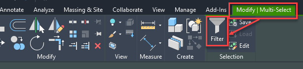
From this filter option uncheck the objects you don't want in your selection set and then click Apply and the OK button.
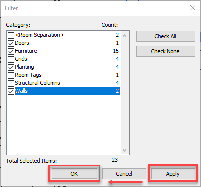
You will now have a selection that contains only your selected type of objects.
Tip 7: Use View Range
Let's assume you have a complex design with various objects placed on a floor plan like toilet fixture, sink, wall fittings, piping systems, ceiling light fixtures and more.
As you can see most of the objects don’t rest on just the floor.
Some objects like Piping system, Underfloor sewage system is below the floor.
Similarly objects like lightings fixtures are on the ceiling.
Some piping system may be over the ceiling and even inside the wall at an elevation from the ground.
If a normal view rage is applied to a plan these objects may not be visible.
So, in such a scenario you need to change the view range so that all the objects are visible in a single view.
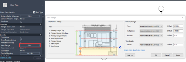
To do so, you can click on the edit button near to the view range option on the properties panel, or you can simply type VR to get the view range dialogue box as shown in the image above.
Tip 8: Use Selection Box
In a project if you want to only see the objects like furniture then you may need to hide all the other objects like walls and floors to make it visible.
But there is a quick way to do just that without hiding anything and its called selection box.
To use it select the object you want to see from the project browser and then from the modify tab select the Selection Box option as shown in the following image.

A new preview with only your selected object inside a box will show up as shown in the following image.
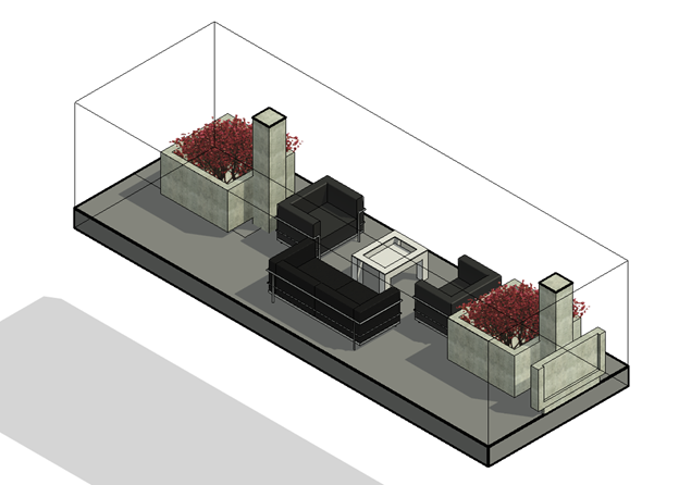
Now you can save this view with a new name, make changes to the objects in it and you can even add it to the sheet.
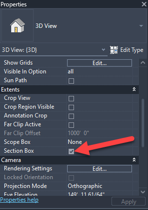
If you want to exit from the selection box, you can simply uncheck the selection box option from the properties palette as shown in the following image.
Tip 9: Autosave and Backup setting
Autosave and backup can save countless hours in the event of a system crash and it is an important thing to configure in Revit.
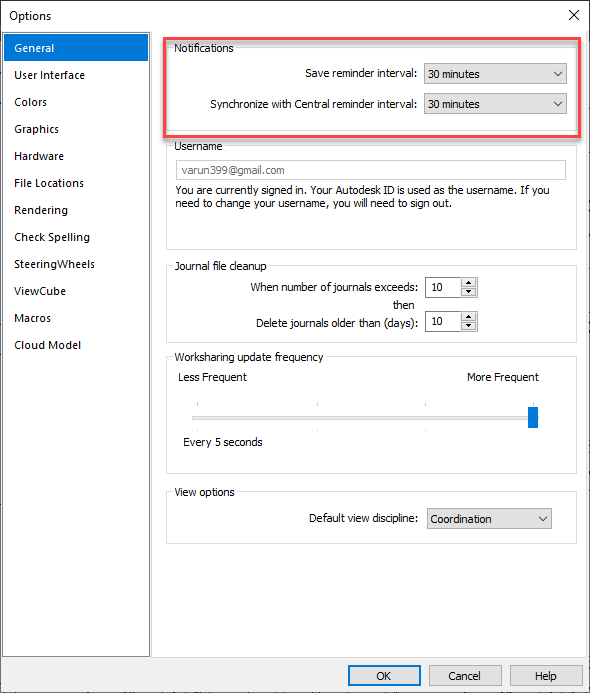
If Autosave is active and you are busy working on your project Revit will remind you to save the project at fixed intervals.
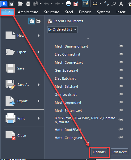
The duration of this notification can be changed from options window as shown in the following image.
When options window shows up select the General tab and there you can select the duration when the autosave reminder will pop up.
Once a Revit file is saved it creates a backup in the same location as the original file which contains the unsaved version of your project.
You can recover your project data from this backup in the worst case scenarios.
If you want Revit to create several backups then you can change that setting too from the options button as shown in the following image.
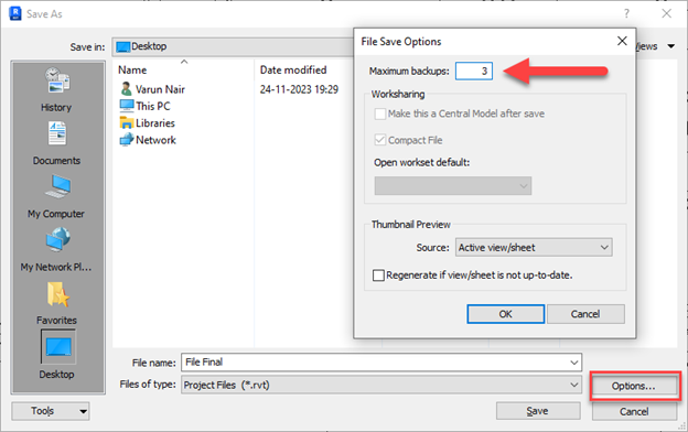
Just be mindful that each backup will take space on your storage drive so you should only keep reasonable number of backups for your project.
Tip 10: Use the right hardware
Revit is quite a demanding software and as the project complexity increases the performance of Revit PC may start to suffer.
So, its important to have hardware that can handle large projects and complex workflows easily.
And to help you select the best hardware for Revit we have created an article listing the best laptop for Revit and all the hardware specs that you should consider when selecting a laptop or PC for Revit.
Tip 11: Set double click action
Several people double click to make selections in other software and that habit can easily pass on to Revit.
But in Revit double clicking on an object will take you to its editing mode.
66 lessons| Easy Level
This course is for an absolute beginner of Revit architecture software. If you want to learn using simple bite sized Revit tutorials and video lessons then this course is for you.
This can be annoying and can create errors as you may end up modifying objects that you don't want.
So, you can change the double click action in Revit as per your preference.
To do that go to Application button (Revit logo at the top left corner) then select the option button as shown in the first image of tip 9.
From the Options window that shows up select the "User Interface" tab and select the "Customize double click setting" as shown in the following image.
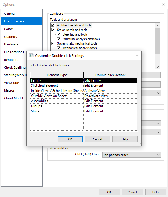
Here you can set double click action to something else for different elements.
Tip 12: Add frequently used folder in open menu
When you are working on a large project for days it quickly becomes annoying when you have to navigate to the folder every time you want to open its files.
You can make this process quick by adding the project folder as a shortcut in the "Open" window.
As you can see in the image below I have added a folder named “Source CAD” into the menu.
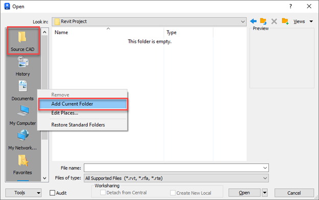
To do that click on the “Open” icon from Application menu bar or quick access toolbar.
Then browse to the location you want to add in the shortcut and then right click in the left panel and select "Add current folder" from the menu.
This will add the folder into the quick list which you can access easily later.
Tip 13: Use Copy monitor
The Copy/Monitor tool of Revit will help you duplicate objects from the linked Revit file.
This feature will be very helpful when you are working with large drawings or collaborating with other designers on their designs.
This feature also keeps monitoring for any changes that happen and alerts the user about the changes made.
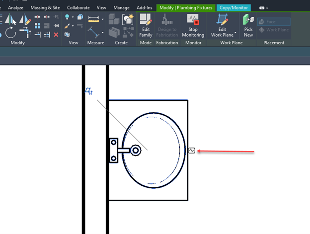
You can access the copy/Monitor option from the Collaborate tab in the ribbon palette under the Coordinate panel as shown in the image below.
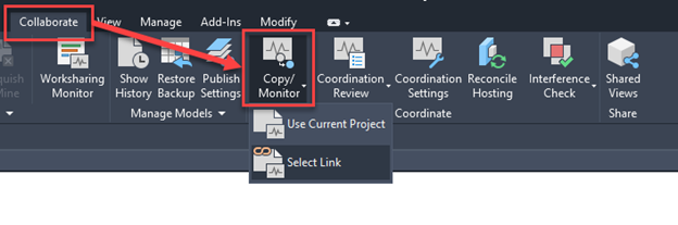
From the Copy/Monitor dropdown select the drawing by browsing to its location using Select Link option or select "Use Current Project" option if the drawing is open.
A Copy/Monitor tab will show up when you select the drawing and from this tab select "Coordination settings" option as shown in the following image.

The Coordination setting will list all the categories of equipment from the selected link and in this setting, you can change the behavior of individual equipment as shown below.
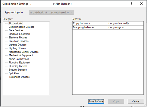
Then you can click "Save and Close" button.
You can also click either on Copy or Batch copy option to copy the equipment or element from the linked drawing.
Below shows an example where individual elements are selected to copy and you can see a monitor logo been shown near the copied object.
Tip 14: Using Linework tool
When you have a multistory building design as shown in the figure below, you may find lines that shows up to separate each floor.
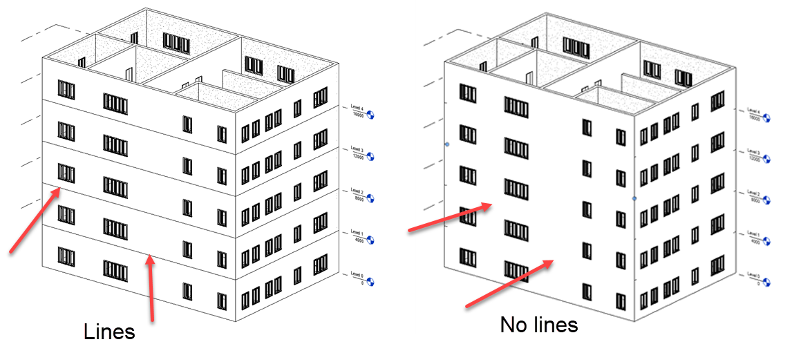
As you can see the line that runs around the building after each floor may not always be required.
So, you can hide these lines.
In Revit we do not have any direct method to hide those lines so we will do it using a workaround.
We will create a line style with the color white so that they get merged with the design.
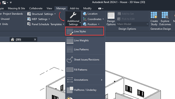
To do that, go to the Manage tab in the ribbon palette and select the Additional setting drop down to select line Style as shown in the following image.
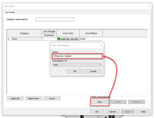
Once you are in the line style dialog box you can click on the new icon under modify subcategory and give any custom name to identify the created line style.
Here I will give a name as “White Line-Custom” and press OK as shown below.
Now that the new line style with the custom name is created you can simply click on the color icon near to line style and select the color white so that it is merged with the wall.
Then click OK to accept the changes as shown in the following image.
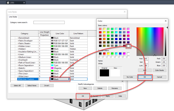
As the line style is created, you can change the line style of the existing lines by clicking on the “Linework” icon under the modify tab or simply type “LW” from the keyboard.
Once the command is activated, you can select the line style from the dropdown under the modify tab as shown below:
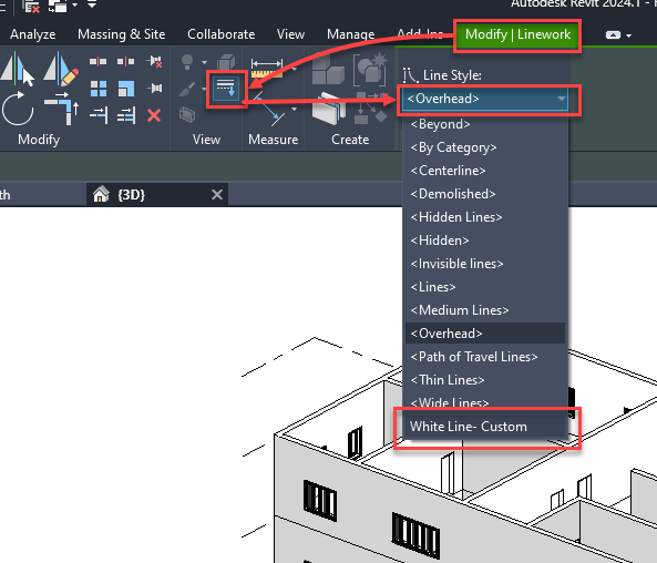
Now select the lines which we want to convert into the new line style.
After that when we click on the lines that used to show the separation between walls it now changes to white, ultimately making it invisible from the drawing.
Tip 15: Wrapping the wall ends
You may have noticed that when you create any specific type of wall with some details the layers assigned to the wall will only be directed along the width of the wall.
Consider the example shown in the image below.
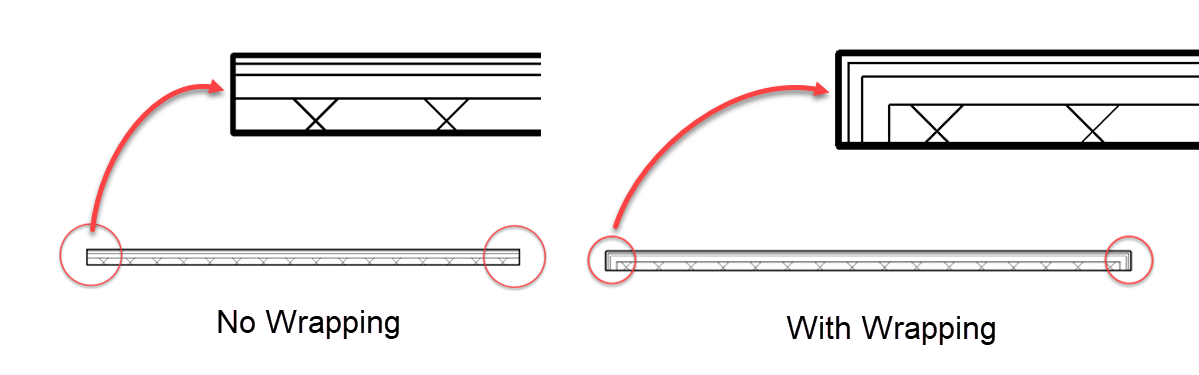
Here you can see that in the wall on left, the details are assigned in layers towards the width, but the same layer pattern is not followed at the end points of the wall.
We can make it to look like the wall.
To make the endpoints of the wall wrapped with the same pattern, you can select the wall, then go to edit type from the properties panel.
In the "Type Parameters" palette select the edit option for the structure as shown below.
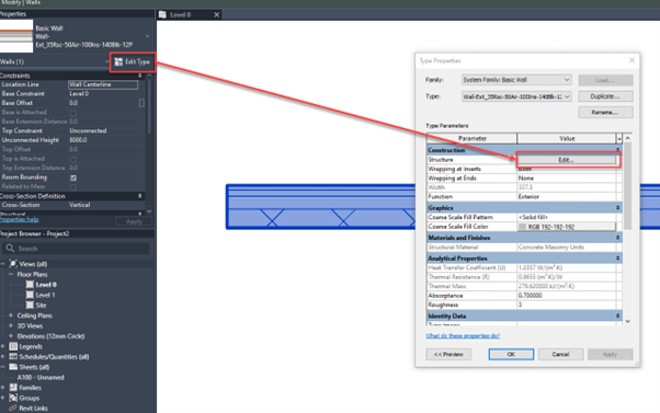
In the edit assembly dialog box, select “Exterior” from the drop down available under the option "At Ends:" under default wrapping properties as shown in the image below.
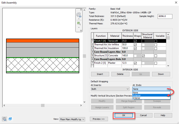
Now you can click OK on both the dialog box and you will see that the end points of the wall are wrapped in the same layer structure as per the wall type.
Tip 16: Combine two types of Walls with elements
Consider an example where we made a normal brick wall with a door and windows as elements added to it.
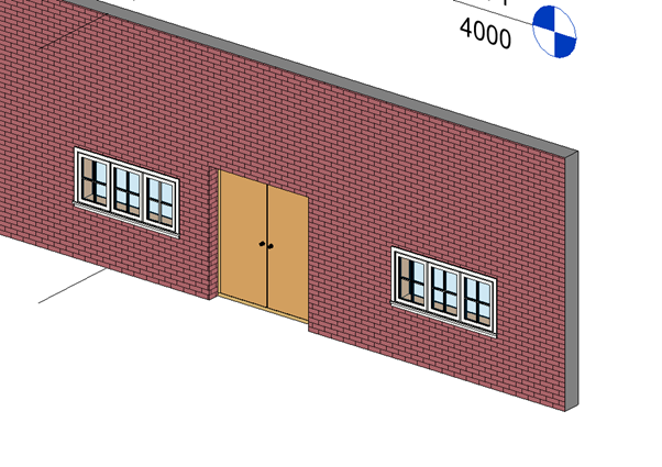
To give the design more polished look I would like to add another layer of wall in front of the existing wall with a different material as well as a custom height.
So once I add that custom made layer wall the design may look like the image given below:
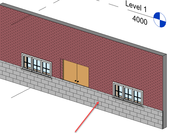
Here you can see that the newly added wall as a layer to the existing wall doesn’t identify the door or windows thus it doesn’t break at the required positions.
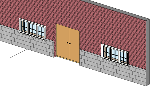
So, to make this correct, we can go to the modify tab in the ribbon pallet and click on the Join Icon under the geometry panel and then select both the walls to join them together as shown in the following image.

After joining both the walls, you can see that the elements or components reflects correctly on both the layers of wall as shown below.
Tip 17: Remove gaps in curtain wall frame
In some scenarios when we insert a curtain wall, you can see gaps in the curtail wall frame on the mullions as shown in the following image.
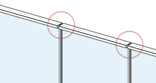
This happens as the curtain wall will have a different dimension for the mullions at the boundary as well as in the interior.
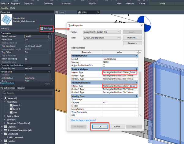
You can check that by selecting the curtain wall and clicking on the edit type icon in the properties panel.
In the "Type Parameters" dialog box, scroll down to Vertical and Horizontal mullions section and there you can see different sizes assigned as shown in the following image.
To remove the gaps in the border or the boundary of the curtain wall, you need to select any one mullion in the panel and click on the icon that pops up at the junction which says “Toggle Mullion Join” as shown in the left side of the following image.
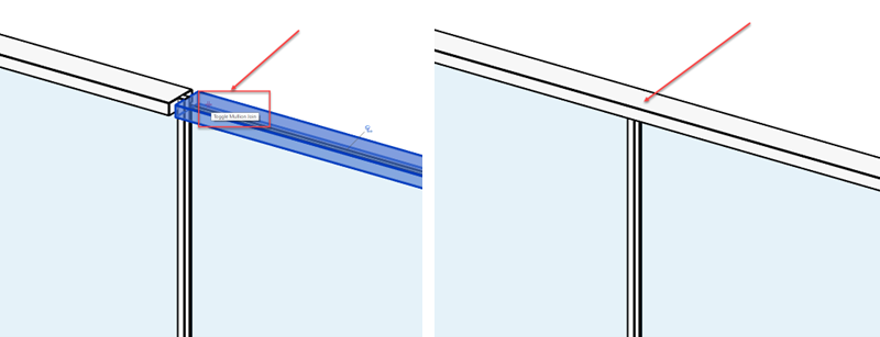
This will join the border to give a seamless design as shown on the right side of the image above.
You can repeat the same process at all the joint locations to merge the gaps.
Tip 18: Editing the profile of a curved curtain wall
If you want to edit the profile of a wall in Revit you can simply click on the object and select the icon "Edit Profile" from the modify tab.
But that is not the case with a curved curtain wall as the "Edit Profile" option is not available for curtain walls.
So, to have a custom shape for a curved curtain wall, you need to follow the steps explained here.
Consider the example below where you have a design with a curved curtain wall as shown in image A below and you want to make it look like image B.
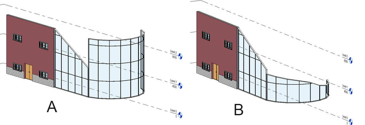
To add a custom profile shape to the curved curtain wall, we need to first go to the floor plan view and click on the reference plane icon from the architecture tab as shown below.

Insert the reference plane in such a way that it lies parallel to the design.
Once the reference plane is inserted you can rename it to a custom name.
Here we named it as “Reference plane_Curtain Wall”.
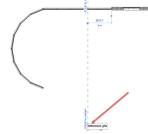
Now you need to open up the elevation view which is perpendicular to the reference plane.
In my case it is the West elevation view, just make sure the Curtain wall is visible in the view.
Now click on the Roof by extrusion icon which you can find under the Architecture tab under the roof dropdown as shown below.
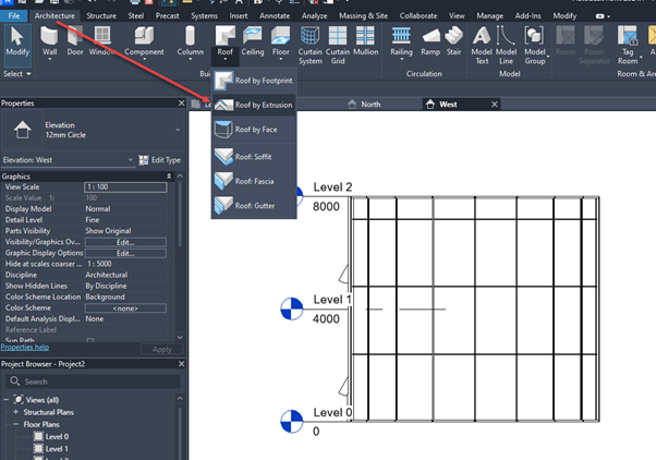
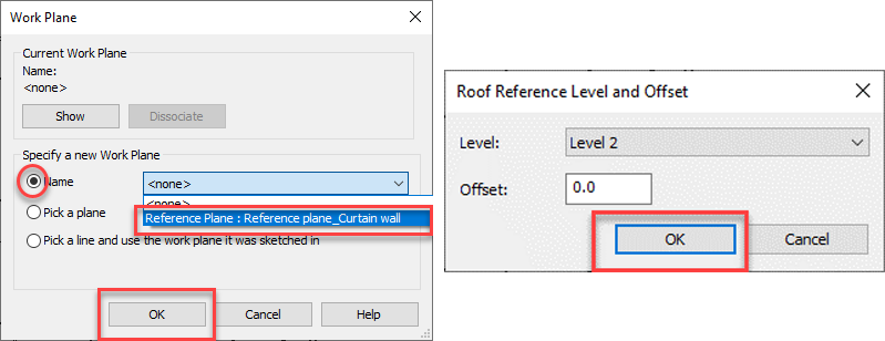
In the Work plane dialog box click on the name option and select the custom plane that you have created earlier and click OK.
Revit will show one more dialog box where you can select any level, after selecting the level click OK as shown in the following image.
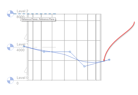
Now create the custom shape that you want as a profile for the curtain wall by using any tool under the modify tab.
I have used the spline tool to draw a custom shape.
Please do note to extend both the sides so that the created extrusion will cover the curtain wall completely as shown below.
Now that you have created the extrusion, you can go to the 3D view and extend the extrusion in such a way it completely crosses the curtain wall as shown below.
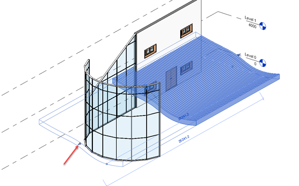
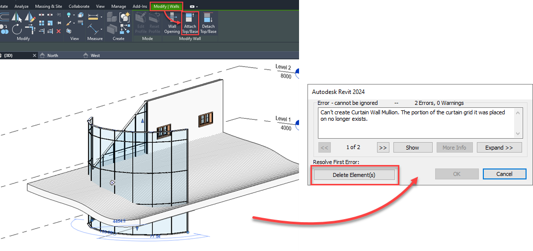
Now you can select the curved curtain wall and select the icon "Attach Top/Base" from the modify tab and select the extruded wall.
If any warning appears you can select the delete element option as shown below.
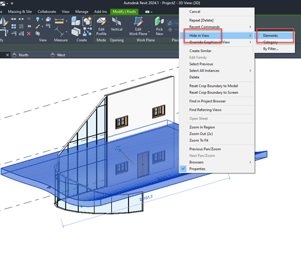
Now that you have the profile created over the curtain wall, you can hide the extruded wall by selecting the wall then right click to find the option "Hide in View" then "Elements" as shown below.
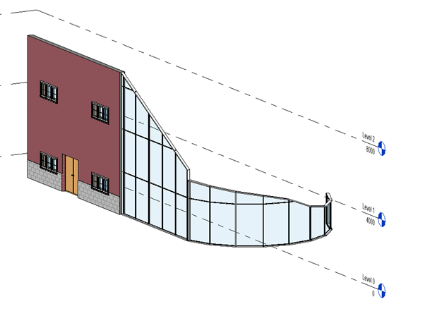
Now you have a complete design with a custom profile made for the curved curtain wall as shown in the image below.
Related reading: Mastering Revit worksets right from scratch.
Revit Structure Tips
The tips in this section are related to Revit Structure software.
Tip 19: Rotate with spacebar
Rotating elements in Revit is made simple with the spacebar shortcut.
Select the element you wish to rotate, press and hold the spacebar, and move the mouse to rotate the element freely.
This intuitive shortcut saves time and allows for precise adjustments to element orientation.
This trick can come in handy in situations where you have a rectangular column, and you want to change it's orientation, as illustrated below.
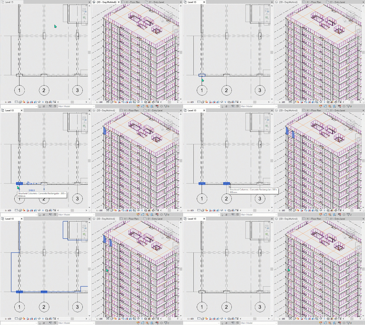
Additionally, you can use it by selecting multiple columns and rotating all of them at once.
Tip 20: Using Character Map to Type Symbols
When adding symbols or special characters to your Revit project, the Character Map tool comes in handy.
Simply open Character Map by either searching for it in the Windows search or the Windows Accessories menu, select the desired symbol, and copy-paste it into your Revit project text fields or annotations as illustrated below.
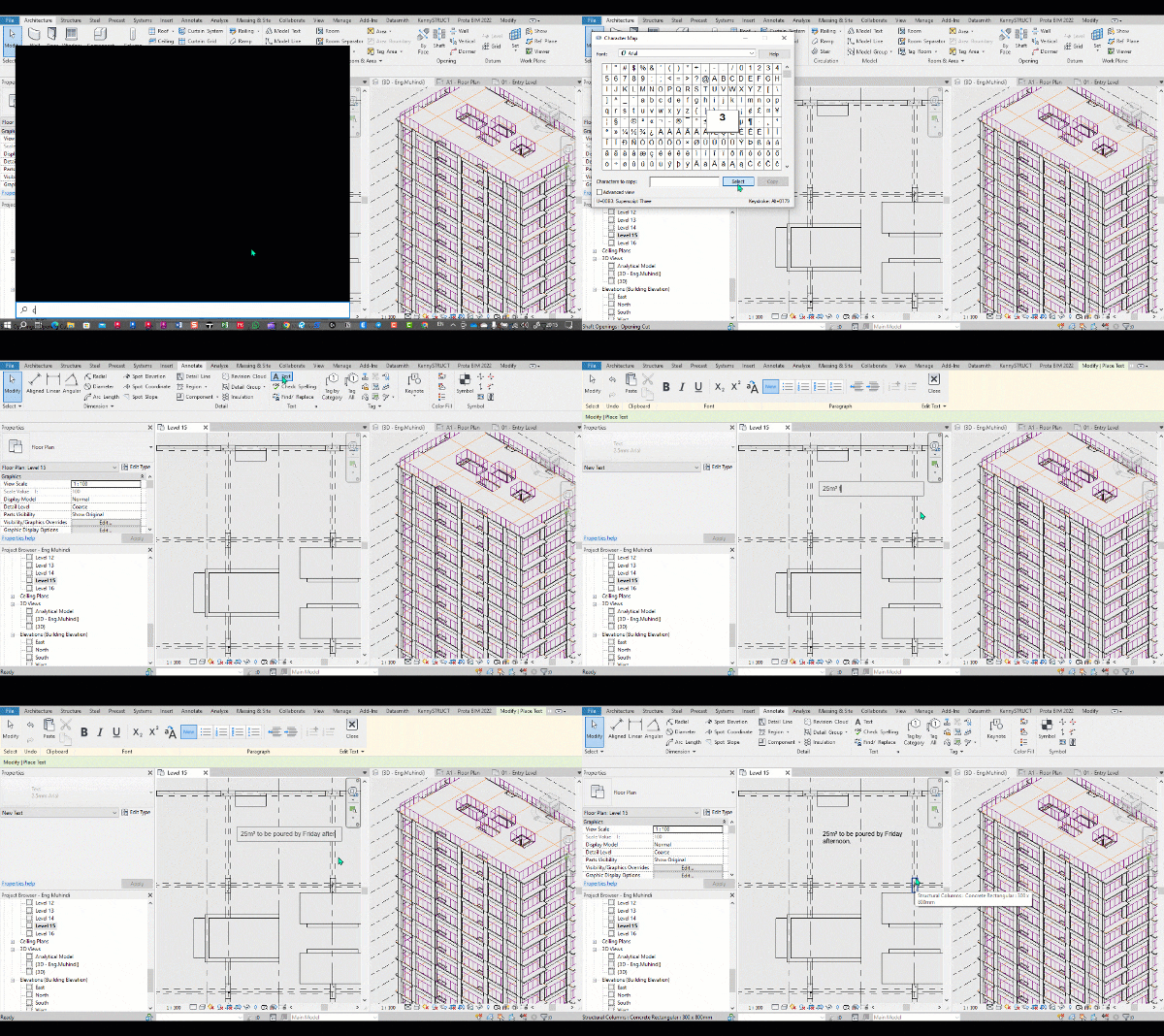
This trick comes in handy if you want to communicate and show some information like volume symbol, diameter, etc.
Tip 21: Use a Starting View to Show Important Information
Starting views in Revit serve as the initial viewpoint when opening a project, making them ideal for showcasing important information or project highlights.
To set a starting view, navigate to the Manage tab under the Manage project panel, click on the starting view command, then a popup window with a list will be shown.
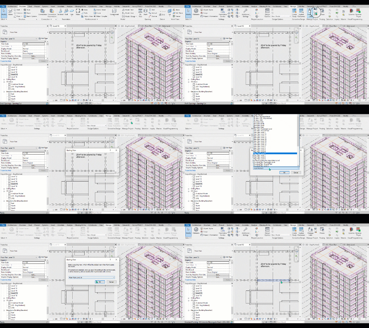
Select your desired view and click on OK, as illustrated above.
Tip 22: Using Section Box to Create a Detail 3D View
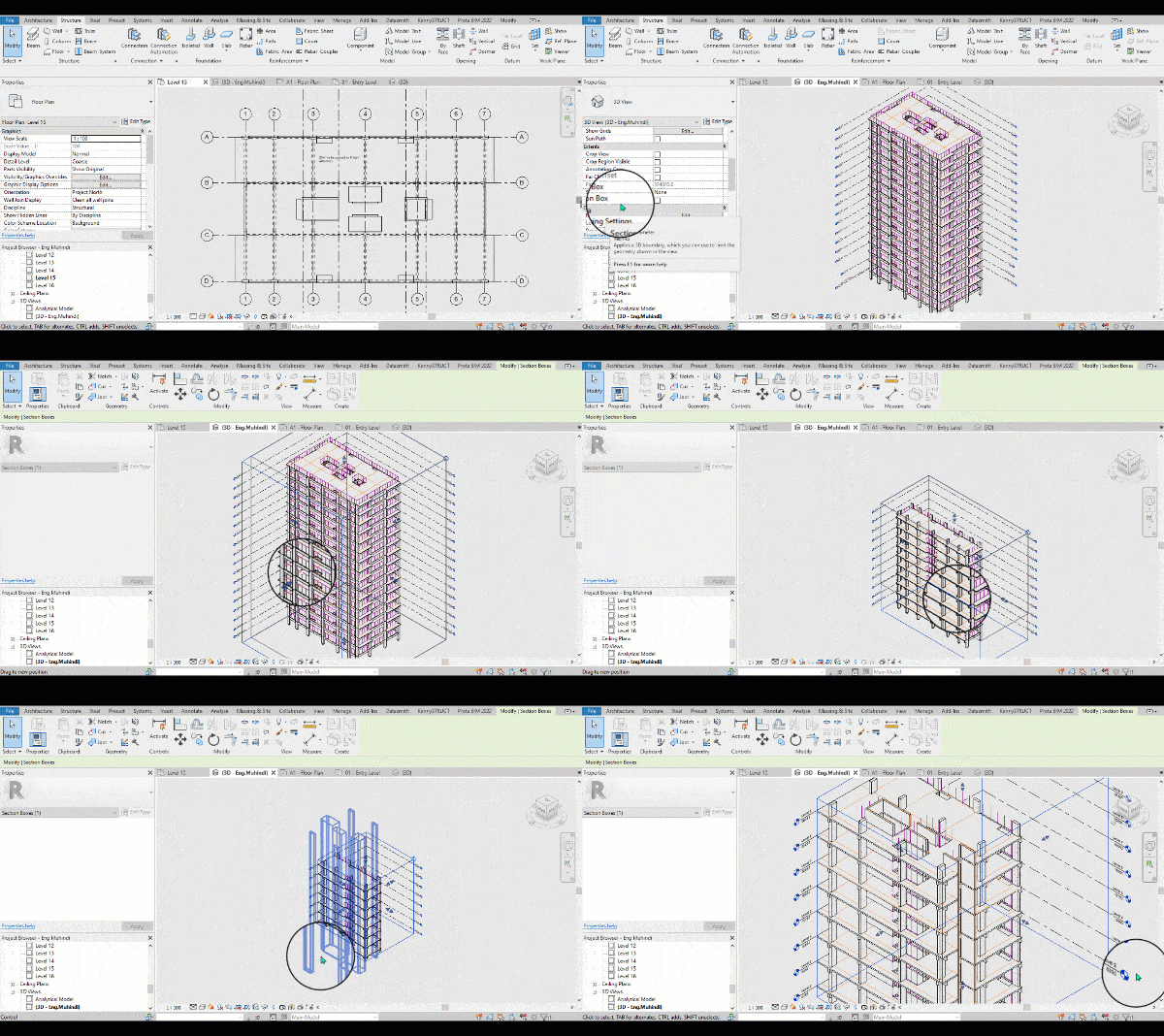
The section box tool in Revit allows you to create detailed 3D views by isolating specific portions of your model.
Simply activate the section box, adjust its dimensions to encompass the desired area, and navigate to a 3D view to see a detailed representation of the selected section.
You can achieve this by first opening your 3D view, then navigate to the Properties view on your left hand side, then to Extents, you will see the section box option.
Make sure to check the box and apply, then the section box will be shown on your 3D model space.
If you left click on the box, it will be active and some grip adjust points will be visible, use them to create our section appropriately as illustrated below.
Tip 23: Create an Exploded View
Creating an exploded view in Revit is a useful technique for visualizing complex assemblies or components.
To do so, first open your 3D view, then select the item you want to displace.
Then navigate to the Modify tab (if does not get activated automatically) and under the view panel, you will see the "Displace Elements" command.
Click on it and a move gizmo will be shown on the object that you selected as illustrated below.
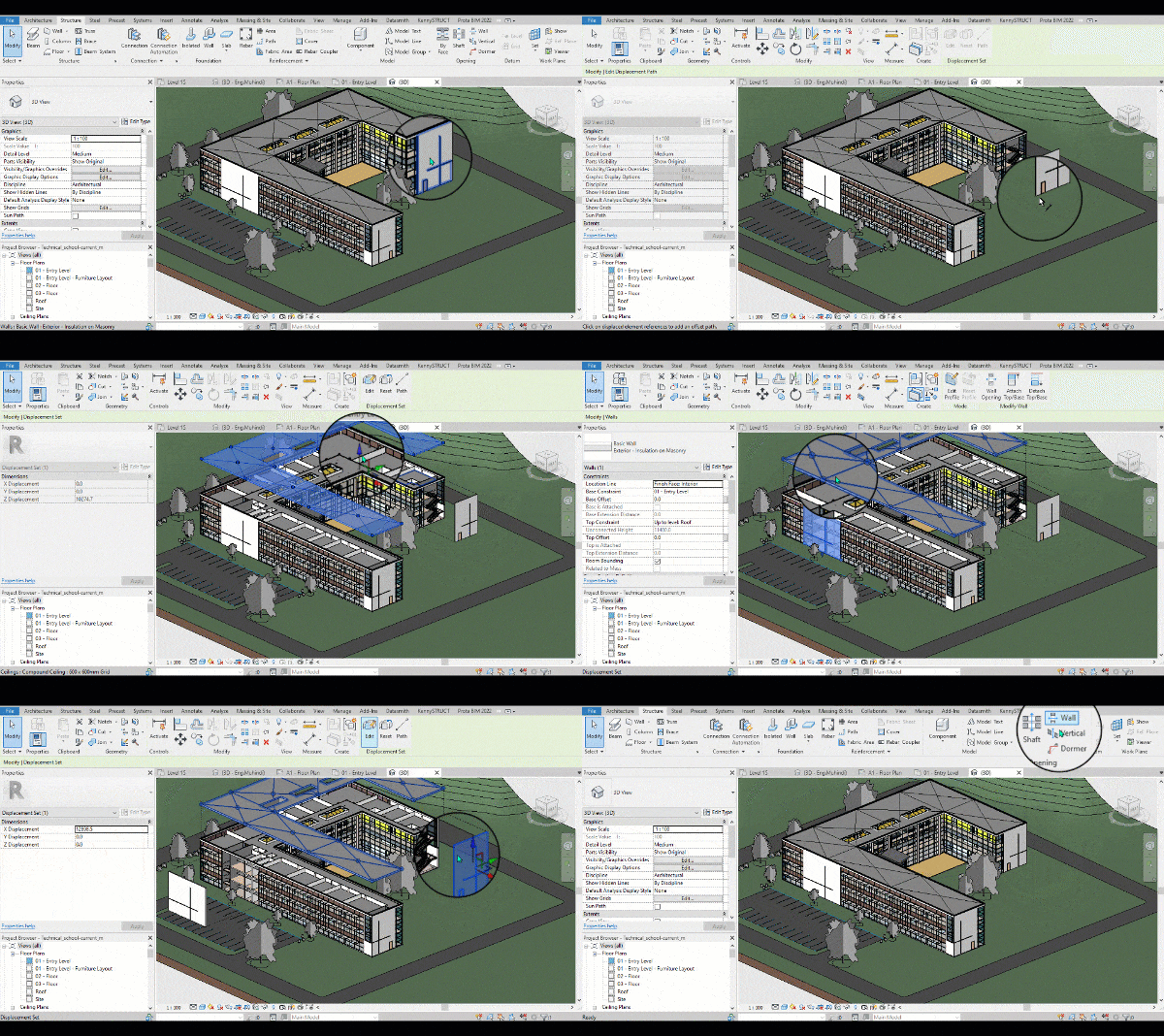
You can move your object either in the X, Y, or Z axes.
This usually creates a clear representation of the assembly's construction sequence or component relationships.
You can also show your displacement path or reset the displacement option just by using the contextual menu that pops up when you select the displaced object.
To exit from the command, simply click on the ESC key on your keyboard.
This trick comes in handy when showcasing your complex Revit structural model in a simplistic way to comprehend.
Tip 24: Purge Unused items in the Model
Regular maintenance of your Revit model is essential for optimal performance.
Use the "Purge Unused" and "Audit" functions under the "Manage" tab to remove unnecessary elements and ensure the integrity of your model's database.
66 lessons| Easy Level
This course is for an absolute beginner of Revit architecture software. If you want to learn using simple bite sized Revit tutorials and video lessons then this course is for you.
You can access this command by navigating to the Manage tab and under the settings panel, you will find the “Purge Unused” command.
If you left-click on it, a list of all items loaded within your project will be shown in a tree format and you can expand the list to see the particular items.
If you click on OK, Revit will purge (remove) all the unused items from your project thus making it lighter as illustrated below.
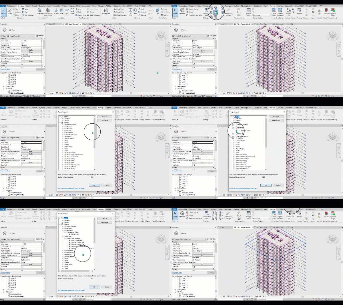
You can be in any view while using this command.
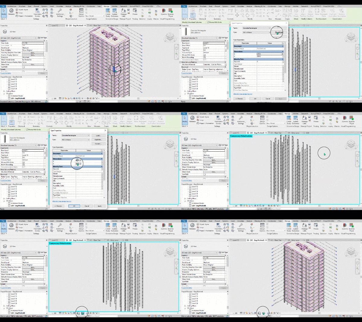
Tip 25: Temporary View and Isolate
Temporary view and isolate options in Revit enable you to focus on specific elements or areas within your project.
Use these tools to temporarily hide or isolate elements, making it easier to work on complex assemblies or navigate cluttered views.
You can use it to isolate a particular category or element or hide a particular element of a category within the temporary view and once you are done, you simply disable it and the changes made will be applied to your model.
You can use it to temporarily isolate all of your columns in your structural model, changing their properties then applying them back to the model as illustrated below.
Tip 26: Creating Polygonal Roofs
Revit's roof tool offers flexibility in creating polygonal roofs with a circle shape.
Under the Architecture tab, select the roof command under the Build panel, once the context menu pops up, select the circle option to draw your roof’s footprint.
Once you have your circle in place, press on the ESC key to exit from the command, then select the footprint, and under the Properties options on your left-hand side, navigate to the constraint options.
You can set the vertices under the "Number of Full segments" option of properties and click on Apply to define the vertices to form the desired shape as illustrated below.
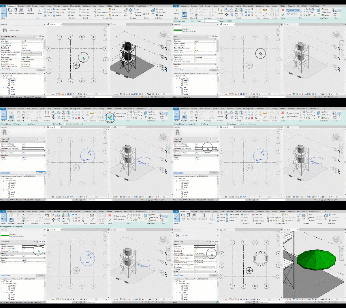
You can also adjust parameters like slope and overhang to customize the roof to your specifications.
This is especially helpful when you want to change number of sides later.
You can change the number of sides from properties and Revit will automatically redesign your roof as illustrated above.
Tip 27: Using View Cube to Find Objects
The view cube in Revit provides a quick and intuitive way to navigate your model in 3D space.
You can use it to find objects that are obstructed from your general view.
For instance, if you have your floor plan open, you can select the item you are interested in e.g. across member beam, then navigate to your 3D view, then using the 3D View cube, click on your “Top-Left” corner and it will zoom the selected item into place as illustrated below.
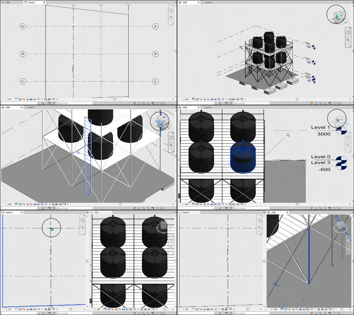
This command can be used to view specific columns that you need to work on.
Related reading: Revit matchline and view reference tools
Revit MEP tips and Tricks
This section contains tips and tricks that are related to Revit Mechanical, Electrical and Plumbing part.
Tip 28: Apply MEP template for existing designs
If you started your design using the Architectural or Structural template and you have designed all the components required apart from the MEP system, then it is still possible to apply the MEP template later.
To do that go to the “Properties” palette, navigate to the “Graphics” settings and click on the “Disciple” option as shown below.
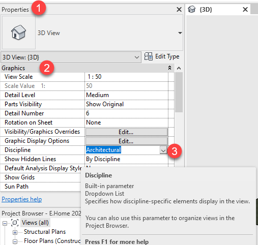
From the available list, select the pre-set template that you require, mechanical, electrical, Plumbing, etc.
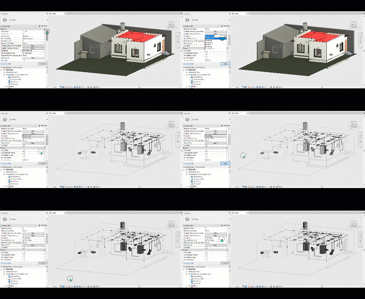
It makes designing components of multiple disciplines seamless without having to save different versions of the same project.
Tip 29: Selecting Routing Preferences
Before starting your design, customize routing preferences to align with industry standards and project requirements.
This includes defining preferred angles, offsets, and connection rules to ensure consistency in your MEP system layout.
Just in case you are wondering, routing preferences dictate how ducts and pipes are routed within your Revit MEP model.
As an example, if you are designing the plumbing system for a high-rise residential building where space is limited, by setting routing preferences to prioritize vertical runs and minimize offsets, you optimize the layout to maximize space efficiency and streamline the installation process.
66 lessons| Easy Level
This course is for an absolute beginner of Revit architecture software. If you want to learn using simple bite sized Revit tutorials and video lessons then this course is for you.
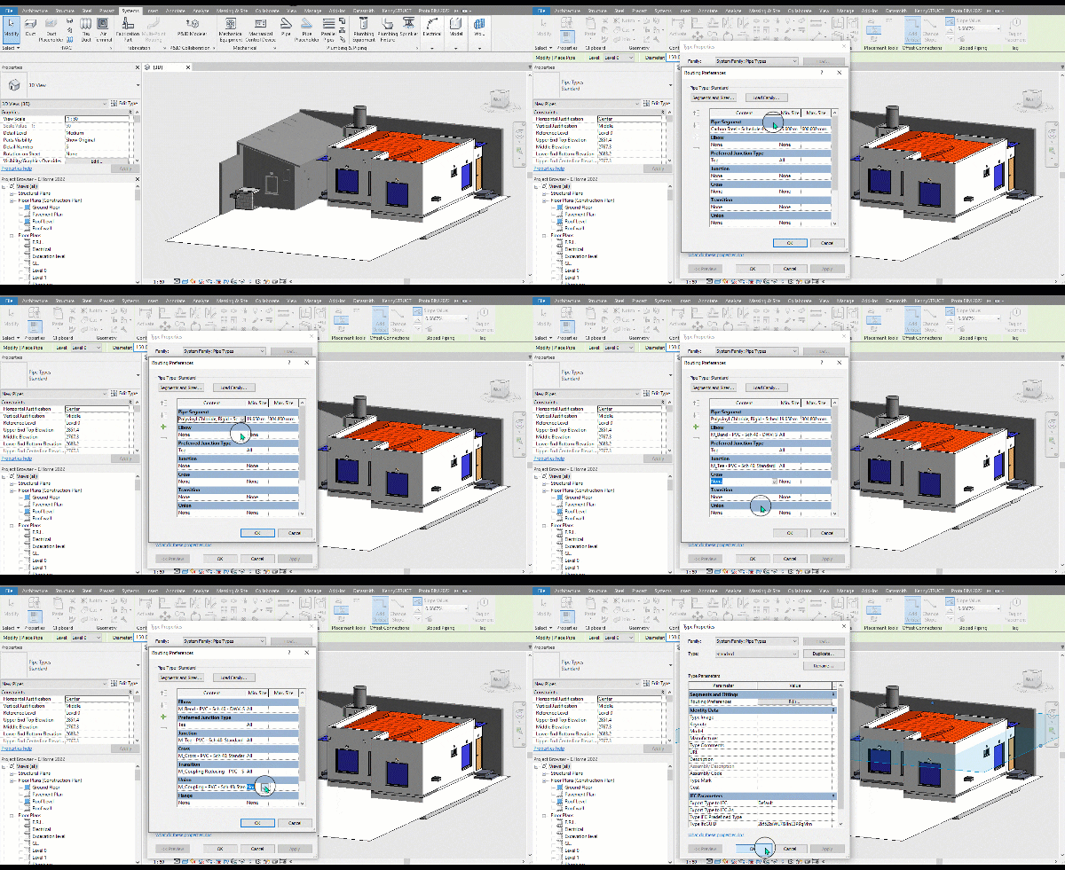
To specify your routing preferences, navigate to the “Systems” tab, and click on either the pipe or HVAC system that you want to create.
In this case, click on the pipe, then under the “Properties” palette, click on “Edit type” then “Type Properties” window and under the “Type Parameter” locate the “Segment and Fittings” option, and under it, you will find the “Routing Preference” setting.
Then click on it to launch it as shown in the following figure.
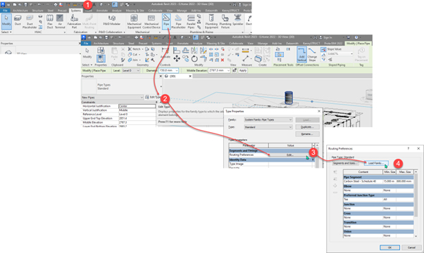
Once launched, you can load the specific family you prefer to use, in this case, use the “PVC” family, then click OK.
Tip 30: Transferring Project Settings
To maintain consistency across multiple projects or collaborate with team members, transferring project settings is essential.
Use the "Transfer Project Standards" feature in Revit MEP to copy project settings, including annotation styles, view templates, and parameter settings, from one project to another.
It ensures uniformity and efficiency in your MEP design workflow.
If you are working on a series of similar projects, such as a chain of retail stores, hotels, schools, etc. with identical MEP requirements, by transferring project settings from a completed project to a new one, you can ensure consistency in design standards and streamline the setup process.
You will find the “Transfer Project Standards” under the “Settings” panel in the “Manage” tab.
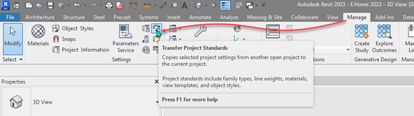
You first need to have the baseline project (the project that you will be copying the standards from) open before clicking the command as shown in the following image.
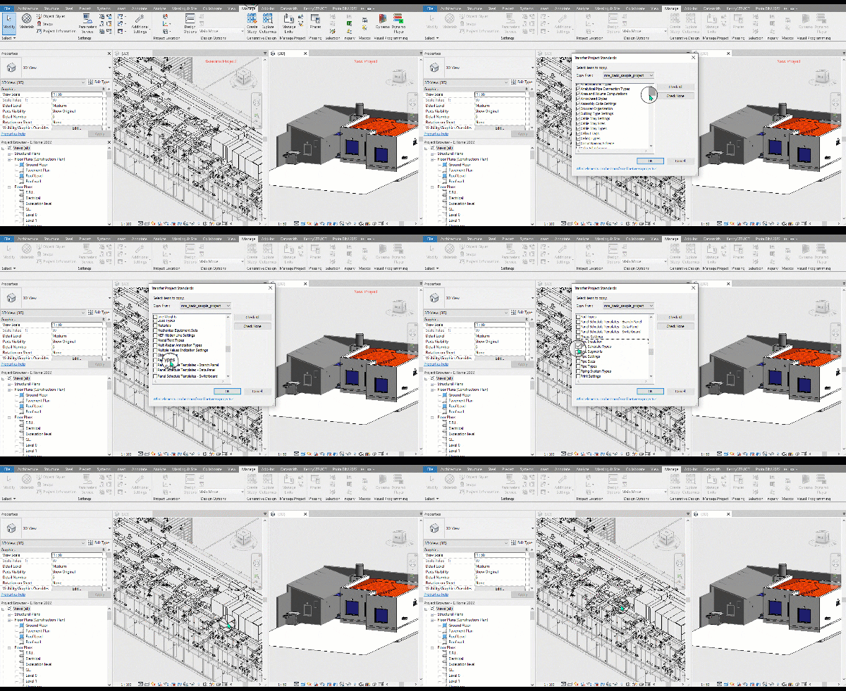
Tip 31: Setting the Elevation for Ducts or Pipes
Precise elevation settings for ducts and pipes are crucial to ensure proper system performance and clearance requirements.
Use the elevation parameter in Revit MEP to set the correct elevation for ducts or pipes, taking into account factors such as ceiling height, structural elements, and accessibility for maintenance.
As an example, if you are designing the HVAC system for an underground parking garage, by accurately setting the elevation for ducts to align with the slab height and clearance requirements, you ensure proper airflow distribution and facilitate ease of installation and maintenance.
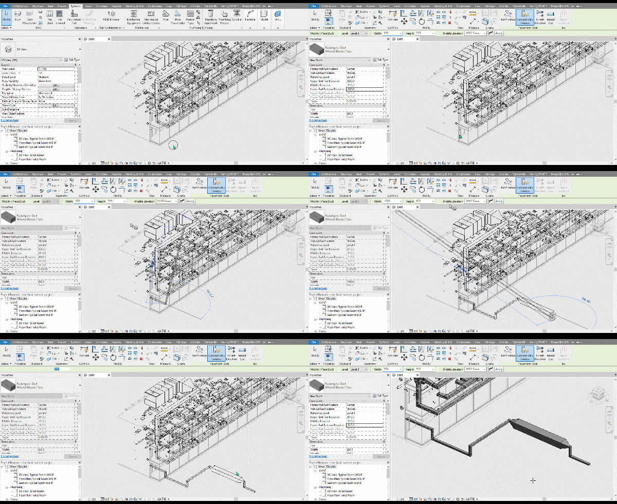
To do that, first select the “Duct” command, under the “HVAC” Panel under the “System” tab.
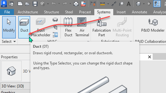
Once the command is active, you can either adjust your elevation parameters from the “Properties” palette or the Contextual ribbon as shown below.
Tip 32: Use of Slopes in MEP Designs
In MEP designs, incorporating slopes in piping systems is essential for efficient drainage and gravity flow.
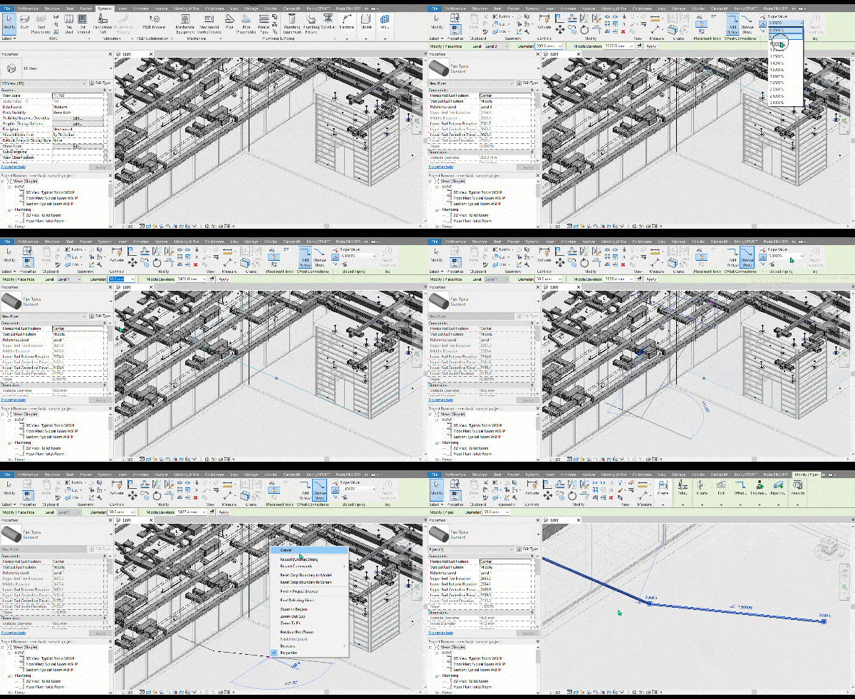
Use the slope parameter in Revit MEP to define the desired gradient for pipes, ensuring proper drainage and preventing water accumulation or stagnation.
If you are designing a sanitary drainage system for a commercial kitchen with multiple sinks, by applying a slope to the drainage pipes, you ensure that wastewater flows efficiently towards the main drain, preventing clogs.
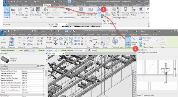
If you select the “Pipe” command located under the “Plumbing & Piping” panel under the “Systems” tab, the “Place Pipe” contextual ribbon will show up.
Navigate to the “Sloped piping” panel and pipe on the type of slope you desire, either slope up or slope down.
Once selected, you can choose the sloping value percentage from the existing slope value list as shown below, then you can design your pipe within the model.
Summary
So, that was our collection of useful Revit Architecture, MEP and Structure tips and tricks.
We also have a collection of Revit courses that you can check to learn more.
Also, if you have a tip that you want to add in this list share it with us in the comments down below.